Safety clutch for heavy duty applications
- Details
- Hits: 13264
The ones presented safety clutches of the ST series R + W are available in four different sizes for torques from 1000 to 160.000 Nm. This makes them particularly suitable for reducing the high downtime costs in heavy machinery construction. Shaft diameters from 40 to 290 mm can be adapted. The couplings are absolutely free of play and maintenance and, compared to other safety couplings, have up to 23% smaller outside diameter.

Contents
- Steel production and heavy engineering
- Comparison of mechanical safety clutches
- Technical data of the slip clutch
- Structure and functional principle of the safety clutch
Steel production and heavy engineering
State-of-the-art steelworks around the world produce all variations and alloys of the metal so that the enormous global demand can be met. In electronic arc furnaces, the base or recycled material is produced in batches of up to 100 t melted down. The subsequent further processing of the steel in continuous casting plants to produce blooms or billets must take place immediately. After a cooling period of several hours, the final step in modern steel production takes place in the rolling mill. In this part of production, the shaping of bar steel (natural gas-fired walking beam furnace) or concrete steel (natural gas-fired pusher furnace) is carried out on different rolling mills.
XNUMX/XNUMX operation
These large-scale systems in heavy engineering construction are or must usually be... 3 shifts 7 days be operated per week. Switching off or shutting down the systems for maintenance intervals of the individual components such as motors, gearboxes, bearings or couplings is avoided if possible, as so-called freezing of the system (e.g. slag bath) must be prevented. As a result, maintenance-free mechanical components are used as far as possible. Overall, the system is safe in normal operation. But what happens outside of normal operations:
- if material fatigue that cannot be detected beforehand occurs in the individual component?
- if a billet gets wedged in the continuous casting plant?
- if an incorrect pressure or an incorrect stroke path is set in the rolling mill?
This is where it stands Cost effectiveness of the system at the top. The large-scale heavy engineering plant must be put back into operation as quickly as possible under all circumstances! At this point, a mechanical safety clutch from R+W Antriebselemente GmbH offers maximum protection against the destruction of the components in the drive train. During the design, the safety clutch is dimensioned by a factor of 1,3 to 2,0 over, for example, the tilting or saddle torque of the motor.
If a crash is imminent during normal operation, the torque increases Powertrain disproportionately. The clutch separates the crash side from the still intact side within milliseconds and prevents total failure of all components. By quickly disconnecting the safety clutch, the fitter only has to replace or clear the blockage in the best case scenario. The maintenance-free and, above all, re-engageable functional principle of the coupling enables the system to be put back into operation in a matter of minutes.
Comparison of mechanical safety clutches
The topic described has been known in heavy-duty mechanical engineering for decades. For the Crash case The designer can choose from breaking bolt couplings or hydraulic couplings. The disadvantages compared to the mechanical safety clutch from R+W are clear. Although a breaker pin coupling is cheaper to purchase, it requires much longer assembly time to put it back into operation.
Characteristics of breaker pin coupling
The Bolzen (usually including bushings) must be completely dismantled. The coupling must then be readjusted before the new pins and sockets can be inserted, which requires enormous assembly effort. The purchase price, which was initially advantageous, is put into perspective by the first triggering process at the latest. Furthermore, putting the clutch back into operation requires a high level of experience on the part of the fitter, because if the clutch is “repaired” incorrectly, it will disengage at different torques in the future! Which in total causes extreme costs during standstills.
An Overload Clutch which works on a hydraulic principle, initially scores points with its extremely compact design. If the clutch releases due to overload, the oil, which is under pressure of up to 1000 bar, is thrown out of the clutch through several shear valves.
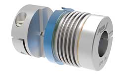 metal bellows coupling | Innovations, applications and special features
The pollution of the machine components in close proximity to the coupling are extreme. After the system has stopped, the individual valves must be replaced and filled with a special pump (exact pressure display). At this point the exact pressure must be maintained, otherwise the release torque will change. In the event of an overload, this hydraulic safety clutch separates the input and output sides to the rated torque. However, the individual components only start to run after a certain time delay. This can potentially lead to further damage to components.
Overall, the mechanical safety clutch combines all of the disadvantages and puts them into perspective. The mechanical functional principle can be put back into operation immediately (disc springs). No wearing parts such as bolts or valves need to be retrofitted. There is no contamination of the component components. But the most important thing at this point is: the installer or the operator of the system has it 100% guaranteed securitythat the clutch disengages at exactly the required torque if damage occurs again. Incorrect restarting is impossible with the R+W principle.
Technical data of the slip clutch
Compared to other mechanical safety clutches, this clutch builds up to 23% more compact in relation to the outside diameter. In the most extreme case, the difference in the total weight of the coupling is 1 t. As a result, significantly higher peripheral speeds can be permitted for the respective coupling sizes. Overall, the new development of the ST safety clutch improves the size, the overall weight and the maximum permissible operating speed.
The individual improvements, especially in terms of size, were directly requested by the market. Because a reduction (up to 73%) enables easier assembly of the coupling. This makes the entire drive train lighter and can possibly be assembled in a pre-assembly process. Finally, the lower overall weight also reduces the moment of inertia due to the lower flywheel masses. In addition to shortening the acceleration and braking process, the system achieves higher dynamics, which ultimately means higher productivity for the end customer.
Structure and functional principle of the safety clutch
 The safety clutch consists of two flanges, which are connected using so-called switching parts (ST). The switching parts are mounted on flange 1 to a defined extent. The ball sitting at the head end can be pressed into the opposite locking segment with a defined force using disc springs. The clutch is adjusted via the physical relationship force x lever arm = torque.
Every switching part can be in one predetermined force range be set. In contrast to the currently available switching segments, the setting range is clearly noted on a scale in R+W's standard. There is no need for complex measurements of the depth of the plunger or conclusions about the disengagement torque using graphics and setting diagrams. The time saving when setting the release torque is clear at this point. Finally, each switching part has a fixed stop in the adjusting nut.
Incorrect operation (locking the clutch) is therefore also impossible. The safety clutch of the ST series extends up to a torque limit of 160.000 Nm. When the clutch is delivered, it is fully functional and requires no additional maintenance or lubrication. Depending on the release torque, there are 3, 6 or 9 switching parts symmetrically distributed around the circumference. The 9 pilot holes provided in all three versions enable the customer to retrofit individual switching parts at any time.
In extreme cases (very compact installation position with extremely high torques) the number of switching parts can be reduced from 9 to 12 or the number of disc springs (higher force) can be increased. This results in an increase in performance of up to 25% of the entire clutch unit. The manufacturer was also able to present improvements in the area of re-locking at the Hanover Fair. A circumferential groove provides a leverage point for better and easier re-engagement of the individual plungers. This advantage reduces the downtime until the system is put back into operation.
ST model series for direct drives
The safety clutch of the ST series is for indirect drives (ST1 model series). Technical parameters such as radial lateral forces caused by chain or belt wheels are compensated for by special shoulder bearings. These bearings also allow an almost unlimited amount of time for the individual flywheels to be braked to a standstill.
The main connection type for the ST1 model series are drive shafts or cardan shafts. These connecting elements are mostly used for power transmission in heavy engineering. Due to the compact design, the outer diameter of the entire cardan shafts is only slightly larger. A simple solution with a connecting flange is offered as a connection to the usually smaller DIN flanges of the cardan shaft.
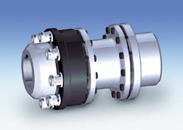
In addition to the indirect drives, two other models for direct drives are available on the market. In addition to the safety segment, the ST2 series has an elastic one compensationelement. This plastic in the form of natural or synthetic rubber compensates for the offsets that occur in the axial, lateral and angular directions. Furthermore, torque surges or vibrations are filtered. The second series for direct drives (model ST3) is offered as a torsion-resistant version. Features include precise torque transmission, very high robustness and compensation for all three types of misalignment that occur with very low restoring forces.